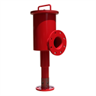
The Chemguard Foam Chamber consists of a foam expansion chamber and an integral foam maker. The foam chamber is installed on a flammable liquid storage tank just below the roof joint. The foam solution is piped to the chamber from outside the hazard area. Upon entering the chamber, the foam solution is expanded and then discharged against a deflector inside the storage tank. The deflector directs the foam against the inside wall of the storage tank. This reduces the submergence of the foam and agitation of the fuel surface.
(NFPA Type II Application)
FEATURES
- U. L. Listed
- (4) models available to cover all flow requirements
- Top of chamber has handle, which simplifies inspection access to the vapor seal
- Frangible glass vapor seal is provided. The glass is scored on one side and designed to break at a minimum 10 psi but not greater than 20 psi.
- Chamber manufactured in ASTM A36 carbon steel with a 304 stainless steel screen covering the foam maker air inlets
- All foam chamber inlets and outlets are flat faced and drilled to ANSI 150 lb. standard. Flange gaskets are provided.
- Choice of two styles of deflector is available (split or solid)
- Finished with durable red epoxy paint
- A stainless steel inlet orifice is supplied. Chemguard sizes the orifice based on the foam solution flow requirements and the foam solution inlet pressure available at the base of the foam chamber.
TECHNICAL DRAWINGS
| Side View |
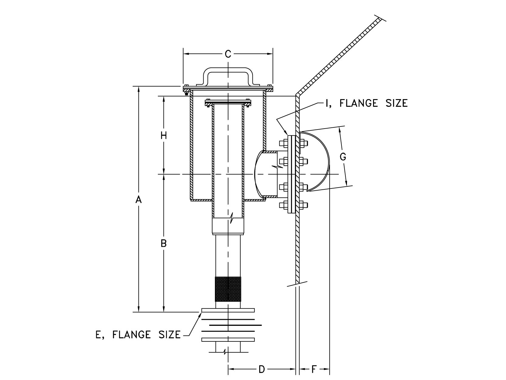 |
| Top View |
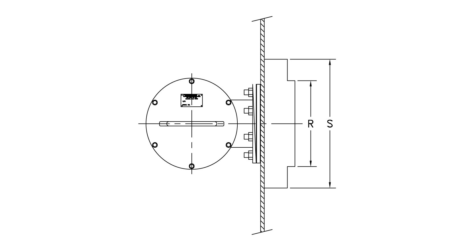 |
| Inlet Flange (E Detail) |
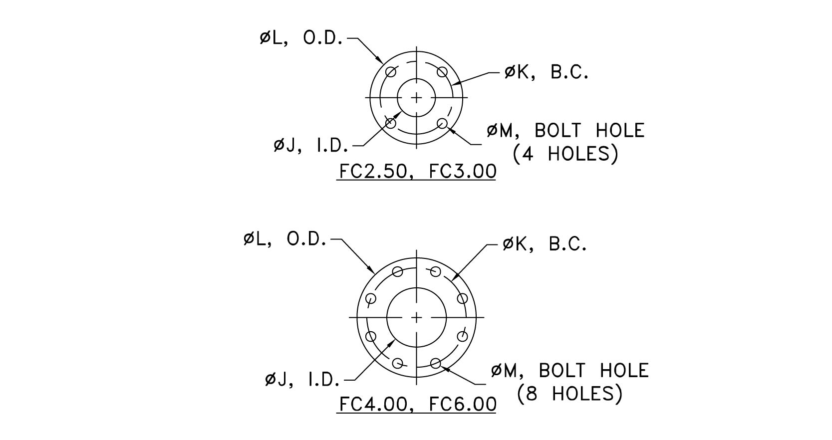 |
| Inlet Flange (I Detail) |
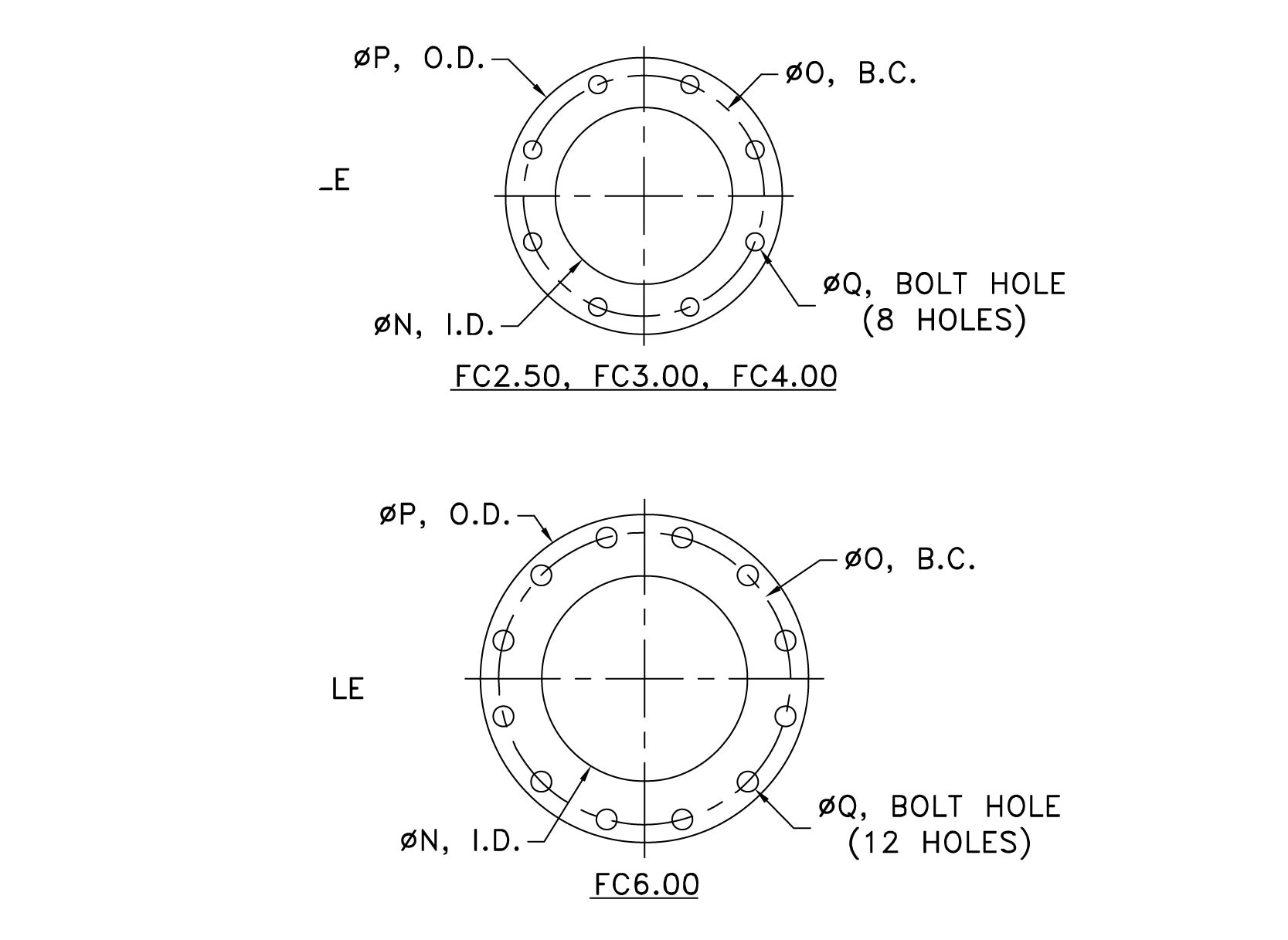 |
| Chamber Dimensions |
 |
PERFORMANCE DATA
| Flow Range Chart - FC2.50 |
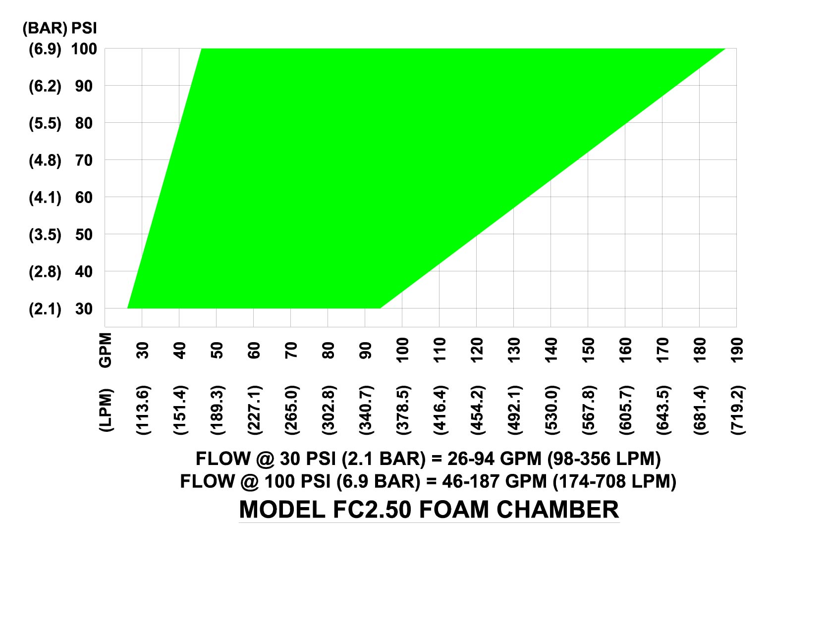 |
| Flow Range Chart - FC3.00 |
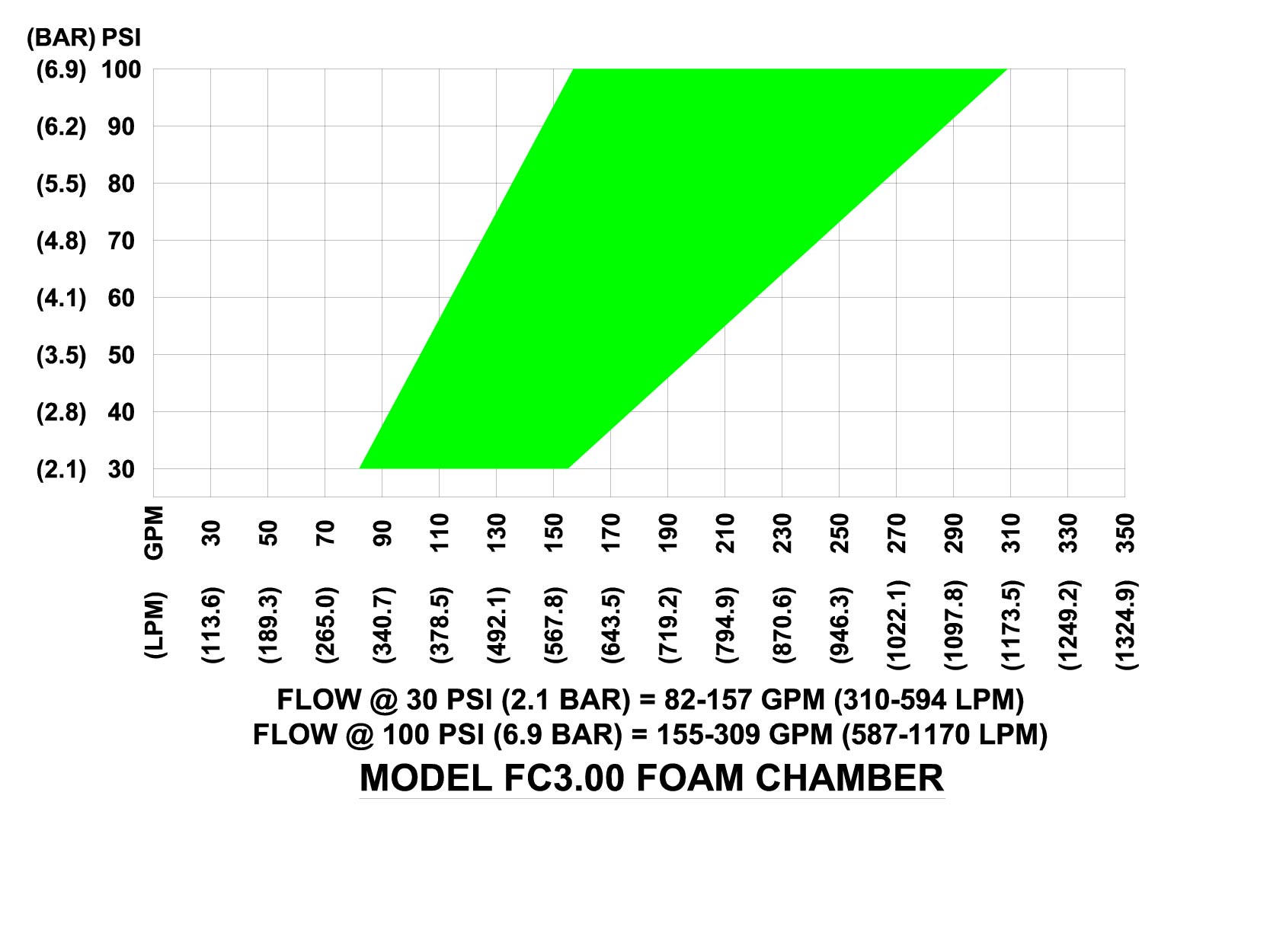 |
| Flow Range Chart - FC4.00 |
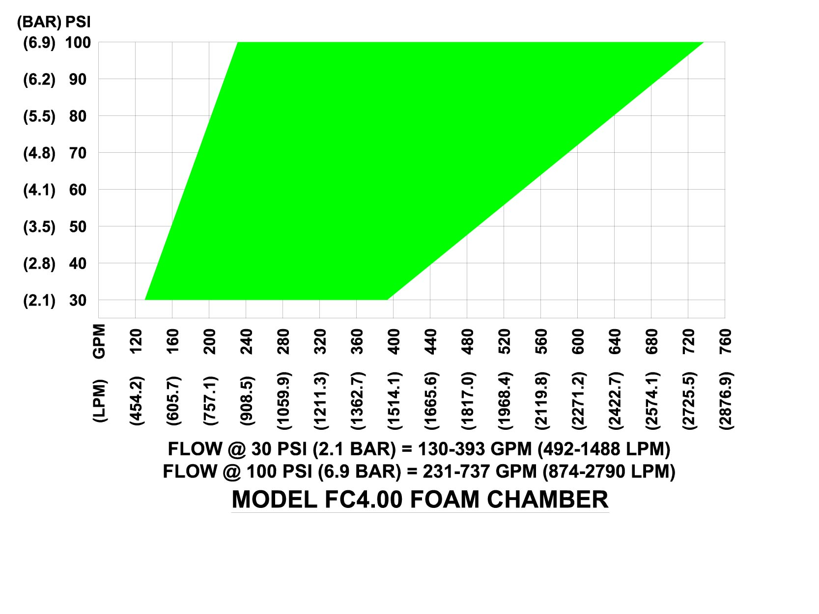 |
| Flow Range Chart - FC6.00 |
 |
NOTE:
1. Solution flow can be specified for any flow/pressure combination within the shaded area.
2. Flows noted at 30 and 100 psi (2.1 & 6.9 bar) are flow achieved through the smallest and largest orifice available for each device.
| Operating Pressure |
 |
| Operating Pressure |
 |
NOTE:
Selection of foam chamber is based upon foam solution pressure at inlet of foam chamber. If this pressure is marginal, always use the ext largest foam chamber size.
ORDERING INFORMATION
When ordering please supply the following:
- Minimum inlet pressure at base of foam chamber and foam solution flow rate required (It is recommended a minimum of 40 PSI inlet pressure be available)
- Type of deflector required - solid or split
- Mounting pad if required
| Part Number |
Flow |
|
FC 2.50
|
58-177 GPM
|
|
FC 3.00
|
101-292 GPM
|
|
FC 4.00
|
180-642 GPM
|
|
FC 6.00
|
540-1090 GPM
|
| Part No: |
Description |
Approx. Shipping Wt. |
GPM |
| Lb. |
(Kg.) |
| FC 2.50 |
2½” Foam Chamber |
60 |
(27.2) |
58-177 GPM |
| FC 2.51 |
2½” Solid Deflector |
5 |
(2.3) |
|
| FC 2.52 |
2½” Split Deflector |
5 |
(2.3) |
|
| FC 2.53 |
2½” Mounting Pad |
15 |
(6.8) |
|
| FC 2.54 |
Spare Vapor Seal Assembly |
1 |
(0.5) |
|
| FC 3.00 |
3” Foam Chamber |
100 |
(45.4) |
101-292 GPM |
| FC 3.01 |
3” Solid Deflector |
10 |
(4.5) |
|
| FC 3.02 |
3” Split Deflector |
10 |
(4.5) |
|
| FC 3.03 |
3” Mounting Pad |
20 |
(9.1) |
|
| FC 3.04 |
Spare Vapor Seal Assembly |
1 |
(0.5) |
|
| FC 4.00 |
4” Foam Chamber |
145 |
(65.8) |
180-642 GPM |
| FC 4.01 |
4” Solid Deflector |
20 |
(9.1) |
|
| FC 4.02 |
4” Split Deflector |
20 |
(9.1) |
|
| FC 4.03 |
4” Mounting Pad |
35 |
(15.9) |
|
| FC 4.04 |
Spare Vapor Seal Assembly |
1 |
(0.5) |
|
| FC 6.00 |
6” Foam Chamber |
270 |
(122.5) |
540-1090 GPM |
| FC 6.01 |
6” Solid Deflector |
30 |
(13.6) |
|
| FC 6.02 |
6” Split Deflector |
30 |
(13.6) |
|
| FC 6.03 |
6” Mounting Pad |
50 |
(22.7) |
|
| FC 6.04 |
Spare Vapor Seal Assembly |
2 |
(0.9) |
|
Note:
Each foam chamber comes complete with the following:
(1) Vapor seal
(1) Orifice - sized per customer requirements
(2) Vapor seal gaskets
(1) Inspection cover gasket
(2) Inlet gaskets
(2) Outlet gaskets
Various nuts, bolts, etc. to make complete assembly.
Deflectors, mounting pads and spare vapor seal assemblies sold separately.